
| | |
This document shows how to properly construct a Crossover network cable. This cable can be used to directly connect two computers to each other without the use of a hub or switch. The ends on a crossover cable are different from each other, whereas a normal 'straight through' cable has identical ends. Their uses are shown in the following diagrams.

Crossover cable use

'Straight Through' cable use
Typically the ports on a hub are MDIX ports. This allows the machine at the other end to utilize its MDI Port (which is what typically a NIC card uses) without the need for a crossover cable. When I say that the ports on the hub are MDIX ports, what I mean is that one of the functions of the hub is to automatically perform the crossover functions, which are required to properly align the cables with each other. When no hub or switch is used, your cable itself must physically perform these crossover functions.
To expand on this a little, when using a hub or switch, the Transmit wires on the workstation need to be connected to the Receive wires on the hub; likewise, the Receive wires on the hub need to be connected to the Transmit wires on the workstation. But if you remember what we stated earlier - cables which are run from PC to Hub are 'straight through' type cables. This is because the hub is providing the required crossover functions internally for you. Thus, when you connect two machines together without the use of a hub or switch, a crossover cable is required - because both 'ends' are essentially the same - a NIC Card. The crossover function must take place somewhere, and since there is no hub or switch to do it for you, the cable must.
Now that we know what a crossover cable is for, let's talk for a few about types of cabling. The two most common unshielded twisted-pair (UTP) network standards are the 10 Mbit (10BASE-T Ethernet) and the 100Mbit (100BASE-TX Fast Ethernet). In order for a cable to properly support 100 Mbit transfers, it must be rated Category 5 (or CAT 5). This type of low loss extended frequency cable will support 10 Base T, 100 Base-T and the newer 100VG-AnyLAN applications. Other types of cabling include Category 3 which supports data rates up to 16 Mbps, and Category 1 which only supports speeds up to 1Mbps. The cable we are about to make is considered Category 5, and will work on both 10 Mbit and 100 Mbit systems, assuming all components used (cables and jacks) are rated for Category 5.
What you need
Cable - Be sure the cable(s) you are using is properly rated for CAT 5. It should state clearly on the jacket of the cable, what it is rated at. One option that you have when selecting your cable is to use a pre-made normal 'straight through' cable, and simply whack off one of the ends, and replace with a new "Crossed Over" end. For the purpose of this article, though, we aren't going to go that route. We are going to make the whole thing from scratch - using bulk CAT 5 cable.
Keep everything within hands reach of you...
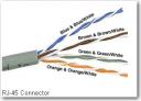
Connectors - Crossover cables are terminated with CAT 5 RJ-45 (RJ stands for "Registered Jack") modular plugs. RJ-45 plugs are similar to those you'll see on the end of your telephone cable except they have eight versus four contacts on the end of the plug. Also, make sure the ends you select are rated for CAT 5 wiring. There are also different types of jacks which are used for different types of cabling (such as Solid Core wire). Make sure you buy the correct jacks for your cabling.
Crimper - You will need a modular crimping tool. My advice on what brand to get? Well, I really don't have a preference at this point, but make sure you buy a good one. If you spend about 40 to 50 bucks, you should have one that will last ya a lifetime. Spend 10 to 20 bucks, and you might be able to make a few cables with it if you're lucky. You definitely get what you pay for when it comes to crimpers!
Stripper - No I'm not talking about what Spot had at his bachelor party, I am talking about a tool to strip the ends off the wires you pervert! There are several specialized tools, which can be used to strip the jackets off of cabling. If you do not have access to one of these tools, cautious use of a razor blade or knife should work just fine - but keep in mind if you go the razor blade / knife route, extra special care must be used as to not damage the wires inside the jacket.
Cutters - You need a pair of cutters that will allow you to cut a group of cables in a straight line. It is very important that all the wires are the same lengths, and without proper cutters, this can be a difficult task.
Doing the deed
You now know what crossover cables are used for. You know why you need one. You also know what you need to make one, so I guess we're ready... First thing you will want to do it cut off the appropriate length of cable that you will need. Be sure that it is plenty long enough. If you screw up, and don't cut it long enough, you will have to start all over, and you will not only waste you time, but cable and the RJ-45 ends as well. If you are pulling this cable through a wall, or ceiling, make sure the pulling is completed first. It is much more difficult to pull a cable with the ends already on it. So you have all the parts, you understand the concepts, and you have your cable, lets get started!
Baby steps...In closing
1) - Start by stripping off about 2 inches of the plastic jacket off the end of the cable. Be very careful at this point, as to not nick or cut into the wires, which are inside. Doing so could alter the characteristics of your cable, or even worse render is useless. Check the wires, one more time for nicks or cuts. If there are any, just whack the whole end off, and start over.
2) - Spread the wires apart, but be sure to hold onto the base of the jacket with your other hand. You do not want the wires to become untwisted down inside the jacket. Category 5 cable must only have 1/2 of an inch of 'untwisted' wire at the end; otherwise it will be 'out of spec'. At this point, you obviously have ALOT more than 1/2 of an inch of un-twisted wire, but don't worry - well take care of that soon enough. 
3) - Up to this point, things have been pretty easy. Things will get a little bit tricky here, but don't worry, we'll get through this together. We are at a point in this article where a decision needs to be made. You need to decide which end of the cable you are making at this point in time. If you are making your cable from scratch like I am doing while writing this article, you have 2 end jacks, which must be installed on your cable. If you are using a pre-made cable, with one of the ends whacked off, you only have one end to install - the crossed over end. Below are two diagrams, which show how you need to arrange the cables for each type of cable end. Decide at this point which end you are making and examine the associated picture below. 
Begin to untwist the twisted exposed wires on your cable. Use caution so that you do not untwist them down inside the jacket. Once you have all the wires untwisted begin to arrange them in the proper order based on the pictures above. This stage can be a pain in the ass, especially some of the middle wires. Once you get all the wired arranged in the proper order, make sure your wire cutters are within reach then grasp them right at the point where they enter the jacket. Make sure you keep them in the proper order! Grab your cutters now. Line them up along your prepared wires about 1/2 inch above the jacket. Be sure at this point that you are both 1/2 inch above the jacket, and that your cutters are aligned straight across the wires. You want to make a clean cut here - also make sure you don't let go of that jacket / wires!


568a - standard end
(you will need one of the ends on
your cable to look like this)Crossed over end wire pattern
(you will want the other end to look
like this)

4) - Don't worry. From this point forward things get a lot easier. Grab your jack, and begin to slide the wires into the jack. Once you get to the point where the jacket begins to enter the jack things might get a little tough, but just have some patience and hold onto those wires. It will fit in there just fine. Once it is in as far as it will go the wires should extend almost to the front of the jack, and about 3/8 of an inch of the jacket will be inside the jack. Like the pictures below.

5) - Grab those crimpers - because not all crimpers are exactly the same your pictures may not match exactly what you see below. Be sure to keep a good grip on that jack and the cable. Insert the jack into the crimper. It should only go in one way, so you don't have a whole lot to worry about inserting it. Begin to compress those crimpers. You will more than likely hear a clicking sound. Keep squeezing. If you try to let go to early, nothing will happen. They will not release. Keep going until they stop clicking / stop moving all together. At this point, you should be able to let go of the jack, and the crimpers. The crimpers should release now leaving you with a crimped jack. If the crimpers do not release, you probably are a wimp and didn't press hard enough. Go ask your mom to help you at this point. She can probably finish what you started.


Insert the jack into the crimper Crimp it! Crimp it good!
6) - It's time to examine what we have done. If you look at the end of the jack (distal), you should see that the copper connectors should not be pressed down into the wires. Toward the back of the jack (where the jacket meets the jack) it should be crimped securely holding the jacket / cable in the jack. If something has gone wrong, don't worry, its not the end of the world. Grab those cutters, and just whack the whole jack off and start back at step 1 (a pain in the ass I know, but its better to have a cable that works, than to spend hours trouble shooting your PC trying to figure out why you can't see the other machine). If everything is cool, all you have to do now is make the other end of the cable (unless you are using a pre-fab cable and have whacked one of the ends off), so go back to step one, and make the other end now.

You should now have a fully functional CAT 5 Crossover cable. It's a good idea to label it as such, especially if you have a lot of other cables lying around. So what are ya waiting for... install the cable and test it out. If it doesn't work, double-check the ends. There is always a possibility that you have overlooked something. If so just whack the bad end and make new one. Remember the more jacks you install, and the more cables you make, the easier it gets. It's really not that hard to do, the first time is definitely the most difficult.
Here are a few other things to keep in mind...
- Maximum Cable length for including connectors is 100 meters (or about 328 feet)
- Do not allow the cable to be sharply bent, or kinked, at any time. This can cause permanent damage to the cables' interior
- Do not overtighten cable ties
- Do not use excessive force when pulling cable through floors, walls or ceilings
- Do not use staples to secure category-5 cable, use the proper hangers, which can be found at most hardware stores
RJ-45 Crossover Cable and Straight Through Pinouts
Overview
This article provides connectivity examples for hub-to-hub, hub-to-transceiver, transceiver-to-transceiver, pinouts and color coding for standard ethernet cabling.
Discussion
|  |
| ||||||||||||||||||||||||


This cable is required to connect the network card in the computer to the correct jack in the wall. The connector on this cable looks very similar to one used for a phone cable, however it is slightly larger. The cable itself is also thicker and less flexible than a standard phone cable. If you do not have the correct cable they can be purchased from the University Bookstore.
For ResNet you need a Category 5 (Cat 5) straight-through Ethernet cable. Crossover and straight-through cables are both RJ-45 network cables. It can be difficult to tell the difference between a standard straight-through Ethernet cable and a crossover cable since they look virtually identical from the outside and neither cable is always clearly marked.
The easiest way to tell the difference between a crossover cable and a straight-through cable is to hold both ends of the cable with both ends facing up (copper connectors showing) and look at the order (left to right), of the coloured wires in the clear plastic connectors. A standard "straight through" Ethernet cable will have the wires in exactly the same order at both ends. In a crossover cable, the order of the coloured wires is different on each end.

Straight-through cable ends

Crossover cable ends
Please note that the University cannot guarantee support for configurations which do not meet the minimum requirements outlined in the Recommended Computer Configuration. Students using such configurations may not have full use of ResNet. In the event that the use of such configurations causes network complications, students will be required to disconnect from the network.
Making Cross and Straight network cableSTEP 1
Choose the right cable
1. To Connect PC to PC Cross Cable.
2. To Connect PC to HUB/SWITCH/ROUTER Straight Cable.
3. To Connect HUB/SWITCH/ROUTER to HUB/SWITCH/ROUTER Cross Cable
STEP 2
Understanding CAT 5 Cables
Wires: CAT 5 Cable has 4 pairs of copper wire inside it.
Colors: Standard cables has BROWN, BROWN WHITE, GREEN, GREEN-
WHITE, BLUE, BLUE WHITE, ORANGE, ORANGE WHITE.
STEP 3
Making Straight Cable
Nomenclature: let us first give a number scheme for cabling which we will follow throughout this tuto. BROWN (8), BROWN WHITE (7), GREEN (6), GREEN WHITE (3), BLUE (4), BLUE WHITE (5), ORANGE (2), ORANGE WHITE (1)
Requirements: Two RJ45 Connectors, Crimping tool & CAT 5 cable of desired
length(less than 250 meters).
STEP 3.1
| Just an additional info, jargons are only for knowledge: There are two standards adopted for Cabling EIA/TIA 568A & EIA/TIA 568B. (for ease consider these standard as a coloring standard on connector's end) When you use single standard (either EIA/TIA 568A or EIA/TIA 568B) on both the end of cable then the resulting cable is STRAIGHT CABLE. On the other hand if you use different cabling standard on the ends of cable then the resulting cable is CROSS CABLE I’ll use EIA/TIA 568B standard for creating cross and straight cable |
1. Remove the covering of CAT 5 cable.
2. Straighten the eight wires of the cable.
3. Using Crimping tool’s cutter cut the end of wires so that they are of same
length
4. Arrange the wire in order 1, 2, 3, 4, 5, 6, 7 & 8 respectively as I have
mention or as shown in the diagram.
5. Insert the arranged cable in the RJ45 connector with clip pointing down
exactly as shown in the figure.
6. In crimping tool insert the head of RJ45 connector and crimp (press) it
hardly.
7. Follow same step with same color order for the other end of cable too.
8. The wire you made by following these steps is a STRAIGHT cable.
STEP 4
Making CROSS Cable
Of the Eight wires in Cat 5 not all are used for data transfer when using 100Mbps Ethernet card. Only 2 pairs of cable are used i.e. 2 wire for transmitting signal and two wires for receiving signal.
Following diagram describes what I want to say:
So now you can guess why we have to make CROSS CABLE for connecting same kind of devices. Because if use same color coding on both the side than transmitter of one m/c will send data to transmitter of another and data packets will lost, so we have to change wiring code so that transmitter of one connects to reciver of other and vice-versa.
Reference diagram:
Here are the Steps:
Steps 1 to 6 are same as for STRAIGHT through cables
7. Only difference is in color coding of other side of wire.
8. Wire that is on 1st number on A-side (one end) should be on 3rd number
on B-side (other side) & vice-versa.
9. Wire that is on 2st number on A-side (one end) should be on 6rd number
on B-side (other side) & vice versa.
10. Now Crimp the RJ45 connector.
11. Your CROSS wire is completed
How to Crimp Connectors|
Kabel UTP sebetulnya ada beberapa kategori yaitu dari kategori 1 - 7 yang sering digunakan untuk LAN biasanya kategori 5 atau sering disebut cat-5. Berikut ini kegunaan dari kabel kategori 1 - 7 diambil dari wikipedia.
- cat 1: sebelumnya dipakai untuk POST (Plain Old Telephone Service) telephone dan ISDN.
- cat 2: dipakai untuk token ring network dengan bw 4mbps
- cat 3: dipakai untuk data network dengan frequensi up to 16Mhz dan lebih populer untuk pemakaian 10mbps
- cat 4: Frequensi up to 20Mhz dan sering dipakai untuk 16mbps token ring network.
- cat 5: Frequensi up to 100Mhz dan biasa dipakai untuk network dengan kecepatan 100Mbps tetap kemungkinan tidak cocok untuk gigabyte ethernet network.
- cat 5e: Frequensi dan kecepatan sama dengan cat-5 tetapi lebih support gigabyte ethernet network.
- cat 6: Memiliki kecepatan up to 250Mbps atau lebih dari dua kali cat-5 dan cat-5e
- cat 6a: Kabel masa depan untuk kecepatan up to 10Gbps
- cat 7: di design untuk bekerja pada frequensi up to 600Mhz.
Berikut ini contoh gambar kabel UTP yang sudah dipasang konektor, kabel cat-5e dalam keadaan terkupas dan kabel cat-6.
alat yang di gunakan meliputi : RJ-45 dengan 8 pin, Crimp Tool, Kabel Tester
Setelah anda tahu alat-alat yang diperlukan untuk pemasangan kabel UTP ke RJ-45 soket, sekarang ada istilah dalam stright dan crossover dalam cabling.
Dari 8 kabel (4 pair) UTP kabel, yang terpakai sebetulnya hanya 4 kabel (dua pair). dua kabel untuk TX atau transfer data dan dua kabel untuk RX atau menerima data. Walaupun hanya empat kabel yang terpakai, kita tidak boleh sembarangan mengambil kabel mana saja yang akan dipakai. Kabel yang dipakai haruslah dua pair atau dua pasang. Tanda kabel satu pasang adalah kabel tersebut saling melilit dan memiliki warna / stripe yang sama. Menurut standar TIA/EIA-568-B pasangan kabel yang dipakai adalah pasangan orange-orange putih dan hijau-hijau putih.
Sementara pin yang dipakai dari delapan pin yang dimiliki RJ-45 yang terpakai adalah Pin nomor 1-2-3-6 sementara nomor 4-5-7-8 tidak terpakai untuk transfer dan receive data Alias nganggur.

Susunan kabel berdasar TX dan RX
Crossover / cross cable adalah kabel yang secara manual maping signal output pada satu konektor ke input di konektor yang satu nya lagi atau TX + dari satu konektor di Maping ke RX + di konektor yang lain dan TX - di konektor yang satu ke RX - di konektor yang lain.


Networking Guide : Cat 5 Wiring Scheme
Straight-through cable is a Cat 5 cable that has similar wiring in both ends. Both cable ends follow either 568A or 568B. If you buy a Cat 5 cable, a practical way to check if it is a straight-through cable is by laying the two ends (connectors) side by side and verifying the colors order. If the colors in both ends are in the same order, it is a straight-trough cable. A straight-through cable is used to connect a computer to a hub or a switch. It can also be used to connect two hubs (or switches) if each hub (or switch) has an uplink (i.e. built-in crossover) port.
Figure: Crossover Cable Wiring.
| |
Crossover cable is a Cat 5 cable that has one end following 568A and the other 568B. A crossover cable is used to connect two computers directly, that's without a hub or a switch. However some computer models have auto-crossover (a.k.a. auto-switching or auto-MDI/MDIX) port that lets a computer connect directly to another computer using a straight-through cable. A crossover cable is also used to connect two hubs (or switches) if both hubs (or switches) don't have uplink ports. The wiring inside a crossover cable is illustrated in the picture above.

very nice
ReplyDeletewow...!
ReplyDeletesuper very nice
Thanq very much
ReplyDelete