Thursday, February 5, 2009

cross cable__


Below is the wiring diagram of both the Straight Through and Cross-Over cables:

Straight Through Cable


CAT5 Cable :// Palmetto Networks

Cross-Over Through Cable

CAT5 Cross-Over Cable :// Palmetto Networks


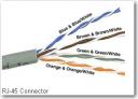
RJ45 Clip ( Registered Jack 45 Clip)

An connecter used to connect 4 pair ( 8 wire) Unshielded Twisted Pair (UTP) cable. RJ-45 connectors look similar to the RJ-11 connectors used for connecting telephone equipment, but the RJ45 somewhat wider than RJ11.

The tool used to connect RJ45 with Unshielded Twisted Pair (UTP) cable, is called ' Crimping tool'

There are lot of crimping tools available with RJ45+RJ11 support.

We can make two types Unshielded Twisted Pair UTP network cables by changing the wire combinations.

  • 1) Crossover cable
  • 2) Straight Through cable

Crossover Cable

Crossover cable can be used to directly connect two computers

to each other without the use of a hub or switch in networking. It also used to connect two hubs or switch without the use of an uplink port in LAN to expand the network.

How to make Crossover Ethernet Cable:

  1. Strip off about 2 inches of the cable sheath.
  2. Untwist the pairs - don't untwist them beyond what you have exposed, the more untwisted cable you have the worse the problems you can run into.
  3. Align the colored wires according to the diagrams below.
  4. Trim all the wires to the same length, about 1/2" to 3/4" left exposed from the sheath.
  5. Insert the wires into the RJ45 end - make sure each wire is fully inserted to the front of the RJ45 end and in the correct order. The sheath of the cable should extend into the RJ45 end by about 1/2" and will be held in place by the crimp.
  6. Crimp the RJ45 end with the crimper tool
  7. Verify the wires ended up the right order and that the wires extend to the front of the RJ45 end and make good contact with the metal contacts in the RJ45 end.
  8. Cut the cable to length - make sure it is more than long enough for your needs. Remember, an end to end connection should not extend more than 100m (~328ft). Try to keep cables short, the longer the cable becomes the more it may affect performance, usually noticable as a gradual decrease in speed and increase in latency.
  9. Repeat the above steps for the second RJ45 end.
  10. If a cable tester is available, use it to verify the proper connectivity of the cable.

That should be it, if your cable doesn't turn out, look closely at each end and see if you can find the problem. Usually a wire ended up in the wrong place or more commonly, one of the wires didn't extend to the front of the RJ45 connector and is making no, or poor contact. If you see a mistake or problem, cut the end off and start again.

Straight Through Cable

Straight-through cables are used for a variety of connections.
e.g.

  • Connecting a computer to a hub or switch,
  • Connecting a computer to a cable/ISDN/DSL modem,
  • End-user devices (e.g., printers) to networking devices such as hubs and switches.

Straight-through: A straight-through network cable is just what the name implies, a cable that passes data straight through from one end to another.

It can also be used to directly connect like devices (e.g., two hubs or two switches) if the cable is plugged into an uplink port on one (but not both) of the devices. Crossover cable is used to connect two like devices without the use of an uplink port.

How to make Straight Through Ethernet Cable:

Follow the same steps in Cross cable method, except aligning the colored wires.
Align the colored wires according to the diagrams below.


cross cable..

How To Make a Crossover Cable


Introduction
This document shows how to properly construct a Crossover network cable. This cable can be used to directly connect two computers to each other without the use of a hub or switch. The ends on a crossover cable are different from each other, whereas a normal 'straight through' cable has identical ends. Their uses are shown in the following diagrams.


Crossover cable use


'Straight Through' cable use


Typically the ports on a hub are MDIX ports. This allows the machine at the other end to utilize its MDI Port (which is what typically a NIC card uses) without the need for a crossover cable. When I say that the ports on the hub are MDIX ports, what I mean is that one of the functions of the hub is to automatically perform the crossover functions, which are required to properly align the cables with each other. When no hub or switch is used, your cable itself must physically perform these crossover functions.

To expand on this a little, when using a hub or switch, the Transmit wires on the workstation need to be connected to the Receive wires on the hub; likewise, the Receive wires on the hub need to be connected to the Transmit wires on the workstation. But if you remember what we stated earlier - cables which are run from PC to Hub are 'straight through' type cables. This is because the hub is providing the required crossover functions internally for you. Thus, when you connect two machines together without the use of a hub or switch, a crossover cable is required - because both 'ends' are essentially the same - a NIC Card. The crossover function must take place somewhere, and since there is no hub or switch to do it for you, the cable must.

Now that we know what a crossover cable is for, let's talk for a few about types of cabling. The two most common unshielded twisted-pair (UTP) network standards are the 10 Mbit (10BASE-T Ethernet) and the 100Mbit (100BASE-TX Fast Ethernet). In order for a cable to properly support 100 Mbit transfers, it must be rated Category 5 (or CAT 5). This type of low loss extended frequency cable will support 10 Base T, 100 Base-T and the newer 100VG-AnyLAN applications. Other types of cabling include Category 3 which supports data rates up to 16 Mbps, and Category 1 which only supports speeds up to 1Mbps. The cable we are about to make is considered Category 5, and will work on both 10 Mbit and 100 Mbit systems, assuming all components used (cables and jacks) are rated for Category 5.


What you need
Cable - Be sure the cable(s) you are using is properly rated for CAT 5. It should state clearly on the jacket of the cable, what it is rated at. One option that you have when selecting your cable is to use a pre-made normal 'straight through' cable, and simply whack off one of the ends, and replace with a new "Crossed Over" end. For the purpose of this article, though, we aren't going to go that route. We are going to make the whole thing from scratch - using bulk CAT 5 cable.


Keep everything within hands reach of you...


Connectors - Crossover cables are terminated with CAT 5 RJ-45 (RJ stands for "Registered Jack") modular plugs. RJ-45 plugs are similar to those you'll see on the end of your telephone cable except they have eight versus four contacts on the end of the plug. Also, make sure the ends you select are rated for CAT 5 wiring. There are also different types of jacks which are used for different types of cabling (such as Solid Core wire). Make sure you buy the correct jacks for your cabling.

Crimper - You will need a modular crimping tool. My advice on what brand to get? Well, I really don't have a preference at this point, but make sure you buy a good one. If you spend about 40 to 50 bucks, you should have one that will last ya a lifetime. Spend 10 to 20 bucks, and you might be able to make a few cables with it if you're lucky. You definitely get what you pay for when it comes to crimpers!

Stripper - No I'm not talking about what Spot had at his bachelor party, I am talking about a tool to strip the ends off the wires you pervert! There are several specialized tools, which can be used to strip the jackets off of cabling. If you do not have access to one of these tools, cautious use of a razor blade or knife should work just fine - but keep in mind if you go the razor blade / knife route, extra special care must be used as to not damage the wires inside the jacket.

Cutters - You need a pair of cutters that will allow you to cut a group of cables in a straight line. It is very important that all the wires are the same lengths, and without proper cutters, this can be a difficult task.

Doing the deed
You now know what crossover cables are used for. You know why you need one. You also know what you need to make one, so I guess we're ready... First thing you will want to do it cut off the appropriate length of cable that you will need. Be sure that it is plenty long enough. If you screw up, and don't cut it long enough, you will have to start all over, and you will not only waste you time, but cable and the RJ-45 ends as well. If you are pulling this cable through a wall, or ceiling, make sure the pulling is completed first. It is much more difficult to pull a cable with the ends already on it. So you have all the parts, you understand the concepts, and you have your cable, lets get started!
Baby steps...

1) - Start by stripping off about 2 inches of the plastic jacket off the end of the cable. Be very careful at this point, as to not nick or cut into the wires, which are inside. Doing so could alter the characteristics of your cable, or even worse render is useless. Check the wires, one more time for nicks or cuts. If there are any, just whack the whole end off, and start over.

Step 1 picture

2) - Spread the wires apart, but be sure to hold onto the base of the jacket with your other hand. You do not want the wires to become untwisted down inside the jacket. Category 5 cable must only have 1/2 of an inch of 'untwisted' wire at the end; otherwise it will be 'out of spec'. At this point, you obviously have ALOT more than 1/2 of an inch of un-twisted wire, but don't worry - well take care of that soon enough.

Step 2a picture

3) - Up to this point, things have been pretty easy. Things will get a little bit tricky here, but don't worry, we'll get through this together. We are at a point in this article where a decision needs to be made. You need to decide which end of the cable you are making at this point in time. If you are making your cable from scratch like I am doing while writing this article, you have 2 end jacks, which must be installed on your cable. If you are using a pre-made cable, with one of the ends whacked off, you only have one end to install - the crossed over end. Below are two diagrams, which show how you need to arrange the cables for each type of cable end. Decide at this point which end you are making and examine the associated picture below.

Step 2b picture Step 2c picture
568a - standard end
(you will need one of the ends on
your cable to look like this)
Crossed over end wire pattern
(you will want the other end to look
like this)

Begin to untwist the twisted exposed wires on your cable. Use caution so that you do not untwist them down inside the jacket. Once you have all the wires untwisted begin to arrange them in the proper order based on the pictures above. This stage can be a pain in the ass, especially some of the middle wires. Once you get all the wired arranged in the proper order, make sure your wire cutters are within reach then grasp them right at the point where they enter the jacket. Make sure you keep them in the proper order! Grab your cutters now. Line them up along your prepared wires about 1/2 inch above the jacket. Be sure at this point that you are both 1/2 inch above the jacket, and that your cutters are aligned straight across the wires. You want to make a clean cut here - also make sure you don't let go of that jacket / wires!

Step 3 picture


4) - Don't worry. From this point forward things get a lot easier. Grab your jack, and begin to slide the wires into the jack. Once you get to the point where the jacket begins to enter the jack things might get a little tough, but just have some patience and hold onto those wires. It will fit in there just fine. Once it is in as far as it will go the wires should extend almost to the front of the jack, and about 3/8 of an inch of the jacket will be inside the jack. Like the pictures below.

Step 4 picture


5) - Grab those crimpers - because not all crimpers are exactly the same your pictures may not match exactly what you see below. Be sure to keep a good grip on that jack and the cable. Insert the jack into the crimper. It should only go in one way, so you don't have a whole lot to worry about inserting it. Begin to compress those crimpers. You will more than likely hear a clicking sound. Keep squeezing. If you try to let go to early, nothing will happen. They will not release. Keep going until they stop clicking / stop moving all together. At this point, you should be able to let go of the jack, and the crimpers. The crimpers should release now leaving you with a crimped jack. If the crimpers do not release, you probably are a wimp and didn't press hard enough. Go ask your mom to help you at this point. She can probably finish what you started.

Step 5a picture Step 5b picture
Insert the jack into the crimper Crimp it! Crimp it good!


6) - It's time to examine what we have done. If you look at the end of the jack (distal), you should see that the copper connectors should not be pressed down into the wires. Toward the back of the jack (where the jacket meets the jack) it should be crimped securely holding the jacket / cable in the jack. If something has gone wrong, don't worry, its not the end of the world. Grab those cutters, and just whack the whole jack off and start back at step 1 (a pain in the ass I know, but its better to have a cable that works, than to spend hours trouble shooting your PC trying to figure out why you can't see the other machine). If everything is cool, all you have to do now is make the other end of the cable (unless you are using a pre-fab cable and have whacked one of the ends off), so go back to step one, and make the other end now.

Step 6 picture
In closing
You should now have a fully functional CAT 5 Crossover cable. It's a good idea to label it as such, especially if you have a lot of other cables lying around. So what are ya waiting for... install the cable and test it out. If it doesn't work, double-check the ends. There is always a possibility that you have overlooked something. If so just whack the bad end and make new one. Remember the more jacks you install, and the more cables you make, the easier it gets. It's really not that hard to do, the first time is definitely the most difficult.

Here are a few other things to keep in mind...
  • Maximum Cable length for including connectors is 100 meters (or about 328 feet)
  • Do not allow the cable to be sharply bent, or kinked, at any time. This can cause permanent damage to the cables' interior
  • Do not overtighten cable ties
  • Do not use excessive force when pulling cable through floors, walls or ceilings
  • Do not use staples to secure category-5 cable, use the proper hangers, which can be found at most hardware stores

RJ-45 Crossover Cable and Straight Through Pinouts

Overview
This article provides connectivity examples for hub-to-hub, hub-to-transceiver, transceiver-to-transceiver, pinouts and color coding for standard ethernet cabling.

Discussion

Crossover Cable
RJ-45 PIN RJ-45 PIN
1 Rx+ 3 Tx+
2 Rc- 6 Tx-
3 Tx+ 1 Rc+
6 Tx- 2 Rc-
Straight Through Cable
RJ-45 PIN RJ-45 PIN
1 Tx+ 1 Rc+
2 Tx- 2 Rc-
3 Rc+ 3 Tx+
6 Rc- 6 Tx-

This cable is required to connect the network card in the computer to the correct jack in the wall. The connector on this cable looks very similar to one used for a phone cable, however it is slightly larger. The cable itself is also thicker and less flexible than a standard phone cable. If you do not have the correct cable they can be purchased from the University Bookstore.

For ResNet you need a Category 5 (Cat 5) straight-through Ethernet cable. Crossover and straight-through cables are both RJ-45 network cables. It can be difficult to tell the difference between a standard straight-through Ethernet cable and a crossover cable since they look virtually identical from the outside and neither cable is always clearly marked.

The easiest way to tell the difference between a crossover cable and a straight-through cable is to hold both ends of the cable with both ends facing up (copper connectors showing) and look at the order (left to right), of the coloured wires in the clear plastic connectors. A standard "straight through" Ethernet cable will have the wires in exactly the same order at both ends. In a crossover cable, the order of the coloured wires is different on each end.

cable_straight.jpg

Straight-through cable ends

cable_cross.jpg

Crossover cable ends

Please note that the University cannot guarantee support for configurations which do not meet the minimum requirements outlined in the Recommended Computer Configuration. Students using such configurations may not have full use of ResNet. In the event that the use of such configurations causes network complications, students will be required to disconnect from the network.

Making Cross and Straight network cable

STEP 1

Choose the right cable

1. To Connect PC to PC Cross Cable.
2. To Connect PC to HUB/SWITCH/ROUTER Straight Cable.
3. To Connect HUB/SWITCH/ROUTER to HUB/SWITCH/ROUTER Cross Cable


STEP 2

Understanding CAT 5 Cables

Wires: CAT 5 Cable has 4 pairs of copper wire inside it.

Colors: Standard cables has BROWN, BROWN WHITE, GREEN, GREEN-
WHITE, BLUE, BLUE WHITE, ORANGE, ORANGE WHITE.


STEP 3

Making Straight Cable

Nomenclature: let us first give a number scheme for cabling which we will follow throughout this tuto. BROWN (8), BROWN WHITE (7), GREEN (6), GREEN WHITE (3), BLUE (4), BLUE WHITE (5), ORANGE (2), ORANGE WHITE (1)

Requirements: Two RJ45 Connectors, Crimping tool & CAT 5 cable of desired
length(less than 250 meters).
STEP 3.1
Just an additional info, jargons are only for knowledge:

There are two standards adopted for Cabling EIA/TIA 568A & EIA/TIA 568B. (for ease consider these standard as a coloring standard on connector's end)

When you use single standard (either EIA/TIA 568A or EIA/TIA 568B) on both the end of cable then the resulting cable is STRAIGHT CABLE.

On the other hand if you use different cabling standard on the ends of cable then the resulting cable is CROSS CABLE

I’ll use EIA/TIA 568B standard for creating cross and straight cable
The figure below very well define the EIA/TIA 568B standard


1. Remove the covering of CAT 5 cable.
2. Straighten the eight wires of the cable.
3. Using Crimping tool’s cutter cut the end of wires so that they are of same
length
4. Arrange the wire in order 1, 2, 3, 4, 5, 6, 7 & 8 respectively as I have
mention or as shown in the diagram.
5. Insert the arranged cable in the RJ45 connector with clip pointing down
exactly as shown in the figure.
6. In crimping tool insert the head of RJ45 connector and crimp (press) it
hardly.
7. Follow same step with same color order for the other end of cable too.
8. The wire you made by following these steps is a STRAIGHT cable.


STEP 4

Making CROSS Cable

Of the Eight wires in Cat 5 not all are used for data transfer when using 100Mbps Ethernet card. Only 2 pairs of cable are used i.e. 2 wire for transmitting signal and two wires for receiving signal.

Following diagram describes what I want to say:


So now you can guess why we have to make CROSS CABLE for connecting same kind of devices. Because if use same color coding on both the side than transmitter of one m/c will send data to transmitter of another and data packets will lost, so we have to change wiring code so that transmitter of one connects to reciver of other and vice-versa.

Reference diagram:


Here are the Steps:
Steps 1 to 6 are same as for STRAIGHT through cables
7. Only difference is in color coding of other side of wire.
8. Wire that is on 1st number on A-side (one end) should be on 3rd number
on B-side (other side) & vice-versa.
9. Wire that is on 2st number on A-side (one end) should be on 6rd number
on B-side (other side) & vice versa.
10. Now Crimp the RJ45 connector.
11. Your CROSS wire is completed

How to Crimp Connectors|

Kabel UTP sebetulnya ada beberapa kategori yaitu dari kategori 1 - 7 yang sering digunakan untuk LAN biasanya kategori 5 atau sering disebut cat-5. Berikut ini kegunaan dari kabel kategori 1 - 7 diambil dari wikipedia.

  • cat 1: sebelumnya dipakai untuk POST (Plain Old Telephone Service) telephone dan ISDN.
  • cat 2: dipakai untuk token ring network dengan bw 4mbps
  • cat 3: dipakai untuk data network dengan frequensi up to 16Mhz dan lebih populer untuk pemakaian 10mbps
  • cat 4: Frequensi up to 20Mhz dan sering dipakai untuk 16mbps token ring network.
  • cat 5: Frequensi up to 100Mhz dan biasa dipakai untuk network dengan kecepatan 100Mbps tetap kemungkinan tidak cocok untuk gigabyte ethernet network.
  • cat 5e: Frequensi dan kecepatan sama dengan cat-5 tetapi lebih support gigabyte ethernet network.
  • cat 6: Memiliki kecepatan up to 250Mbps atau lebih dari dua kali cat-5 dan cat-5e
  • cat 6a: Kabel masa depan untuk kecepatan up to 10Gbps
  • cat 7: di design untuk bekerja pada frequensi up to 600Mhz.

Berikut ini contoh gambar kabel UTP yang sudah dipasang konektor, kabel cat-5e dalam keadaan terkupas dan kabel cat-6.

crimp

alat yang di gunakan meliputi : RJ-45 dengan 8 pin, Crimp Tool, Kabel Tester

Setelah anda tahu alat-alat yang diperlukan untuk pemasangan kabel UTP ke RJ-45 soket, sekarang ada istilah dalam stright dan crossover dalam cabling.
Dari 8 kabel (4 pair) UTP kabel, yang terpakai sebetulnya hanya 4 kabel (dua pair). dua kabel untuk TX atau transfer data dan dua kabel untuk RX atau menerima data. Walaupun hanya empat kabel yang terpakai, kita tidak boleh sembarangan mengambil kabel mana saja yang akan dipakai. Kabel yang dipakai haruslah dua pair atau dua pasang. Tanda kabel satu pasang adalah kabel tersebut saling melilit dan memiliki warna / stripe yang sama. Menurut standar TIA/EIA-568-B pasangan kabel yang dipakai adalah pasangan orange-orange putih dan hijau-hijau putih.
Sementara pin yang dipakai dari delapan pin yang dimiliki RJ-45 yang terpakai adalah Pin nomor 1-2-3-6 sementara nomor 4-5-7-8 tidak terpakai untuk transfer dan receive data Alias nganggur.


                          Susunan kabel berdasar TX dan RX

Crossover / cross cable adalah kabel yang secara manual maping signal output pada satu konektor ke input di konektor yang satu nya lagi atau TX + dari satu konektor di Maping ke RX + di konektor yang lain dan TX - di konektor yang satu ke RX - di konektor yang lain.

Networking Guide : Cat 5 Wiring Scheme

Straight-through cable is a Cat 5 cable that has similar wiring in both ends. Both cable ends follow either 568A or 568B. If you buy a Cat 5 cable, a practical way to check if it is a straight-through cable is by laying the two ends (connectors) side by side and verifying the colors order. If the colors in both ends are in the same order, it is a straight-trough cable. A straight-through cable is used to connect a computer to a hub or a switch. It can also be used to connect two hubs (or switches) if each hub (or switch) has an uplink (i.e. built-in crossover) port.

Ethernet crossover cable wiring
Figure: Crossover Cable Wiring.


Crossover cable is a Cat 5 cable that has one end following 568A and the other 568B. A crossover cable is used to connect two computers directly, that's without a hub or a switch. However some computer models have auto-crossover (a.k.a. auto-switching or auto-MDI/MDIX) port that lets a computer connect directly to another computer using a straight-through cable. A crossover cable is also used to connect two hubs (or switches) if both hubs (or switches) don't have uplink ports. The wiring inside a crossover cable is illustrated in the picture above.

Wednesday, February 4, 2009

TCP/IP....

Introduction to TCP/IP

(pronounced as separate letters) Short for Transmission Control Protocol/Internet Protocol, the suite of communications protocols used to connect hosts on the Internet. TCP/IP uses several protocols, the two main ones being TCP and IP. TCP/IP is built into the UNIX operating system and is used by the Internet, making it the de facto standard for transmitting data over networks. Even network operating systems that have their own protocols, such as Netware, also support TCP/IP

Summary:

TCP and IP were developed by a Department of Defense (DOD) research project to connect a number different networks designed by different vendors into a network of networks (the "Internet"). It was initially successful because it delivered a few basic services that everyone needs (file transfer, electronic mail, remote logon) across a very large number of client and server systems. Several computers in a small department can use TCP/IP (along with other protocols) on a single LAN. The IP component provides routing from the department to the enterprise network, then to regional networks, and finally to the global Internet. On the battlefield a communications network will sustain damage, so the DOD designed TCP/IP to be robust and automatically recover from any node or phone line failure. This design allows the construction of very large networks with less central management. However, because of the automatic recovery, network problems can go undiagnosed and uncorrected for long periods of time.

As with all other communications protocol, TCP/IP is composed of layers:

  • IP - is responsible for moving packet of data from node to node. IP forwards each packet based on a four byte destination address (the IP number). The Internet authorities assign ranges of numbers to different organizations. The organizations assign groups of their numbers to departments. IP operates on gateway machines that move data from department to organization to region and then around the world.
  • TCP - is responsible for verifying the correct delivery of data from client to server. Data can be lost in the intermediate network. TCP adds support to detect errors or lost data and to trigger retransmission until the data is correctly and completely received.
  • Sockets - is a name given to the package of subroutines that provide access to TCP/IP on most systems.

Network of Lowest Bidders

The Army puts out a bid on a computer and DEC wins the bid. The Air Force puts out a bid and IBM wins. The Navy bid is won by Unisys. Then the President decides to invade Grenada and the armed forces discover that their computers cannot talk to each other. The DOD must build a "network" out of systems each of which, by law, was delivered by the lowest bidder on a single contract.

ipdept.gif

The Internet Protocol was developed to create a Network of Networks (the "Internet"). Individual machines are first connected to a LAN (Ethernet or Token Ring). TCP/IP shares the LAN with other uses (a Novell file server, Windows for Workgroups peer systems). One device provides the TCP/IP connection between the LAN and the rest of the world.

To insure that all types of systems from all vendors can communicate, TCP/IP is absolutely standardized on the LAN. However, larger networks based on long distances and phone lines are more volatile. In the US, many large corporations would wish to reuse large internal networks based on IBM's SNA. In Europe, the national phone companies traditionally standardize on X.25. However, the sudden explosion of high speed microprocessors, fiber optics, and digital phone systems has created a burst of new options: ISDN, frame relay, FDDI, Asynchronous Transfer Mode (ATM). New technologies arise and become obsolete within a few years. With cable TV and phone companies competing to build the National Information Superhighway, no single standard can govern citywide, nationwide, or worldwide communications.

The original design of TCP/IP as a Network of Networks fits nicely within the current technological uncertainty. TCP/IP data can be sent across a LAN, or it can be carried within an internal corporate SNA network, or it can piggyback on the cable TV service. Furthermore, machines connected to any of these networks can communicate to any other network through gateways supplied by the network vendor.

Addresses

Each technology has its own convention for transmitting messages between two machines within the same network. On a LAN, messages are sent between machines by supplying the six byte unique identifier (the "MAC" address). In an SNA network, every machine has Logical Units with their own network address. DECNET, Appletalk, and Novell IPX all have a scheme for assigning numbers to each local network and to each workstation attached to the network.

On top of these local or vendor specific network addresses, TCP/IP assigns a unique number to every workstation in the world. This "IP number" is a four byte value that, by convention, is expressed by converting each byte into a decimal number (0 to 255) and separating the bytes with a period. For example, the PC Lube and Tune server is 130.132.59.234.

An organization begins by sending electronic mail to Hostmaster@INTERNIC.NET requesting assignment of a network number. It is still possible for almost anyone to get assignment of a number for a small "Class C" network in which the first three bytes identify the network and the last byte identifies the individual computer. The author followed this procedure and was assigned the numbers 192.35.91.* for a network of computers at his house. Larger organizations can get a "Class B" network where the first two bytes identify the network and the last two bytes identify each of up to 64 thousand individual workstations. Yale's Class B network is 130.132, so all computers with IP address 130.132.*.* are connected through Yale.

The organization then connects to the Internet through one of a dozen regional or specialized network suppliers. The network vendor is given the subscriber network number and adds it to the routing configuration in its own machines and those of the other major network suppliers.

There is no mathematical formula that translates the numbers 192.35.91 or 130.132 into "Yale University" or "New Haven, CT." The machines that manage large regional networks or the central Internet routers managed by the National Science Foundation can only locate these networks by looking each network number up in a table. There are potentially thousands of Class B networks, and millions of Class C networks, but computer memory costs are low, so the tables are reasonable. Customers that connect to the Internet, even customers as large as IBM, do not need to maintain any information on other networks. They send all external data to the regional carrier to which they subscribe, and the regional carrier maintains the tables and does the appropriate routing.

New Haven is in a border state, split 50-50 between the Yankees and the Red Sox. In this spirit, Yale recently switched its connection from the Middle Atlantic regional network to the New England carrier. When the switch occurred, tables in the other regional areas and in the national spine had to be updated, so that traffic for 130.132 was routed through Boston instead of New Jersey. The large network carriers handle the paperwork and can perform such a switch given sufficient notice. During a conversion period, the university was connected to both networks so that messages could arrive through either path.

Subnets

Although the individual subscribers do not need to tabulate network numbers or provide explicit routing, it is convenient for most Class B networks to be internally managed as a much smaller and simpler version of the larger network organizations. It is common to subdivide the two bytes available for internal assignment into a one byte department number and a one byte workstation ID.

classb.gif

The enterprise network is built using commercially available TCP/IP router boxes. Each router has small tables with 255 entries to translate the one byte department number into selection of a destination Ethernet connected to one of the routers. Messages to the PC Lube and Tune server (130.132.59.234) are sent through the national and New England regional networks based on the 130.132 part of the number. Arriving at Yale, the 59 department ID selects an Ethernet connector in the C& IS building. The 234 selects a particular workstation on that LAN. The Yale network must be updated as new Ethernets and departments are added, but it is not effected by changes outside the university or the movement of machines within the department.

A Uncertain Path

Every time a message arrives at an IP router, it makes an individual decision about where to send it next. There is concept of a session with a preselected path for all traffic. Consider a company with facilities in New York, Los Angeles, Chicago and Atlanta. It could build a network from four phone lines forming a loop (NY to Chicago to LA to Atlanta to NY). A message arriving at the NY router could go to LA via either Chicago or Atlanta. The reply could come back the other way.

How does the router make a decision between routes? There is no correct answer. Traffic could be routed by the "clockwise" algorithm (go NY to Atlanta, LA to Chicago). The routers could alternate, sending one message to Atlanta and the next to Chicago. More sophisticated routing measures traffic patterns and sends data through the least busy link.

If one phone line in this network breaks down, traffic can still reach its destination through a roundabout path. After losing the NY to Chicago line, data can be sent NY to Atlanta to LA to Chicago. This provides continued service though with degraded performance. This kind of recovery is the primary design feature of IP. The loss of the line is immediately detected by the routers in NY and Chicago, but somehow this information must be sent to the other nodes. Otherwise, LA could continue to send NY messages through Chicago, where they arrive at a "dead end." Each network adopts some Router Protocol which periodically updates the routing tables throughout the network with information about changes in route status.

If the size of the network grows, then the complexity of the routing updates will increase as will the cost of transmitting them. Building a single network that covers the entire US would be unreasonably complicated. Fortunately, the Internet is designed as a Network of Networks. This means that loops and redundancy are built into each regional carrier. The regional network handles its own problems and reroutes messages internally. Its Router Protocol updates the tables in its own routers, but no routing updates need to propagate from a regional carrier to the NSF spine or to the other regions (unless, of course, a subscriber switches permanently from one region to another).

Undiagnosed Problems

IBM designs its SNA networks to be centrally managed. If any error occurs, it is reported to the network authorities. By design, any error is a problem that should be corrected or repaired. IP networks, however, were designed to be robust. In battlefield conditions, the loss of a node or line is a normal circumstance. Casualties can be sorted out later on, but the network must stay up. So IP networks are robust. They automatically (and silently) reconfigure themselves when something goes wrong. If there is enough redundancy built into the system, then communication is maintained.

In 1975 when SNA was designed, such redundancy would be prohibitively expensive, or it might have been argued that only the Defense Department could afford it. Today, however, simple routers cost no more than a PC. However, the TCP/IP design that, "Errors are normal and can be largely ignored," produces problems of its own.

Data traffic is frequently organized around "hubs," much like airline traffic. One could imagine an IP router in Atlanta routing messages for smaller cities throughout the Southeast. The problem is that data arrives without a reservation. Airline companies experience the problem around major events, like the Super Bowl. Just before the game, everyone wants to fly into the city. After the game, everyone wants to fly out. Imbalance occurs on the network when something new gets advertised. Adam Curry announced the server at "mtv.com" and his regional carrier was swamped with traffic the next day. The problem is that messages come in from the entire world over high speed lines, but they go out to mtv.com over what was then a slow speed phone line.

Occasionally a snow storm cancels flights and airports fill up with stranded passengers. Many go off to hotels in town. When data arrives at a congested router, there is no place to send the overflow. Excess packets are simply discarded. It becomes the responsibility of the sender to retry the data a few seconds later and to persist until it finally gets through. This recovery is provided by the TCP component of the Internet protocol.

TCP was designed to recover from node or line failures where the network propagates routing table changes to all router nodes. Since the update takes some time, TCP is slow to initiate recovery. The TCP algorithms are not tuned to optimally handle packet loss due to traffic congestion. Instead, the traditional Internet response to traffic problems has been to increase the speed of lines and equipment in order to say ahead of growth in demand.

TCP treats the data as a stream of bytes. It logically assigns a sequence number to each byte. The TCP packet has a header that says, in effect, "This packet starts with byte 379642 and contains 200 bytes of data." The receiver can detect missing or incorrectly sequenced packets. TCP acknowledges data that has been received and retransmits data that has been lost. The TCP design means that error recovery is done end-to-end between the Client and Server machine. There is no formal standard for tracking problems in the middle of the network, though each network has adopted some ad hoc tools.


TCP/IP Protocols

The Transmission Control Protocol/Internet Protocol (TCP/IP) standards are always published as RFCs (Request For Comment), but not all RFCs specify standards.

TCP/IP protocols follow the Department Of Defence (DOD) four-layer model:

Application/Process
Transport or Host-to-Host
Internet
Network Access

OSI Model

DOD Model

Application

Application/Process

Presentation

Session

Transport

Transport or Host-to-Host

Network

Internet

Data Link

Network Access

Physical

The TCP/IP protocol suite consists of:

Application/Process Telnet FTP LPD SNMP
TFTP SMTP NFS X window
Host-to-Host

TCP

UDP

Internet ICMP BootP ARP RARP
IP
Network Access Ethernet Fast Ethernet Token Ring FDDI

At the Network layer IP uses NDIS (Network Device Interface Specification) to submit frames to the network layer.

The four protocols at the Internet layer are:

  1. IP. The Internet Protocol is a connectionless and unreliable protocol that addresses and routes packets between hosts. It contains the Source IP of the sender host, the destination IP, the transport protocol (TCP or UDP), checksum and Time to Live (TTL). The TTL is decremented by at least one second each time the IP datagram passes through a router. When TTL reaches zero, the packet is discarded. The default TTL in NT 4.0 is 128 seconds.
  2. ARP. The Address Resolution Protocol obtains the MAC addresse of a host on the same physical network by broadcast and maps it to the host's IP addresse. Once ARP obtains a hardware address, stores both the IP and the MAC address as one entry in the ARP cache. The cache maintains both static and dynamic entries. Dynamic entries are added and deleted automaticaly, where static entries remain in cache until the computer restarts. ARP always checks the cache before it initiates a broadcast. ARP allows two hosts on different subnets to communicate by broadcasting to the default gateway. Each ARP cache entry can live up to 10 minutes. If it is not used within 2 minutes, it is deleted; otherwise, if used, it is deleted after 10 minutes. By adding static ARP entries you decrease the number of ARP requests. To view the ARP cache use the arp -g command.
  3. ICMP. The Internet Control Message Protocol reports errors and control messages on behalf of IP. It is carried by IP datagrams and it is unreliable.
  4. IGMP. The Internet Group Management Protocol passes information to other routers so each router is aware of what hosts belong to what network. It is carried by IP datagrams and it is unreliable.

The two protocols at the Transport or Host-to- Host layer are:

  1. TCP. The Transmission Control Protocol is a reliable, connection-oriented delivery service. It uses byte-stream communications so data is treated as a sequence of bytes. For each data segment sent, the receiving host must return an acknowledgment within a specified period. If there is no acknowledgment, the data is retransmitted. A TCP session is initialized via a three-way handshake in order to synchronize the sending and receiving of data segments. All TCP data segments have two parts: data and header. Sockets applications use a unique port number. Port numbers for well-known server side applications are pre-assigned by IANA and do not change. Port numbers for client-side applications are dynamically assigned by the operating system. A socket is created by an application by specifying the IP of the host, the service type (TCP or UDP) and the port the applications is using.
  2. UDP. The User Datagram Protocol is an unreliable and connectionless datagram service. Is used by applications that do not require acknowledgment of data receipt such as NetBIOS name service and SNMP. UDP ports are separate from TCP ports even though some of them use the same port number.

At the Application layer Microsoft TCP/IP provides two interfaces for network applications: Windows Sockets and NetBIOS. Examples of sockets applications are FTP and Telnet. Examples of NetBIOS applications are net view, net use, etc.

TCP/IP enables you to connect dissimilar systems with utilities such as FTP and Telnet. On NT all TCP/IP utilities are implemented as client software except for FTP which is both client and server. Note that NT can be a SLIP client but not SLIP server, thus NT RAS servers do not accept SLIP client connections.

1. Data transfer utilities:

Trivial File Transfer Protocol (TFTP) works like FTP.
Remote Copy Protocol (RCP) copies files between NT and a Unix host.

  1. Remote execution utilities:

    Telnet provides terminal emulation.
    Remote Shell (RSH) which runs commands on a Unix host.
    Remote Execution (REXEC) which runs a process on a remote computer.

  2. Printing utilities:

    Line Printer Remote (LPR) prints a file to a host running the Line Printing Daemon (LPD) service.
    Line Printer Queue (LPQ) obtains status of a print queue on a host running the LPD service.

  3. Diagnostics utilities:

PING (Packet InterNet Groper)
IPCONFIG
Finger
NSLOOKUP
HOSTNAME
NETSTAT
NBTSTAT
Route
Tracert
ARP

TCP/IP configuration uses an IP address, subnet mask and default gateway to communicate with hosts. Each NIC in a computer that use TCP/IP requires these parameters.

An IP address is a logical 32-bit number that identifies a host. Each IP consists of the network ID and the host ID. The network ID identifies all hosts on the same physical network and the host ID identifies a host on the network.

A subnet mask blocks out a portion of the IP address so that TCP/IP can distinguish the network ID from the host ID. The subnet mask determines if the destination host is on a local or remote network. If a duplicate IP address is configured, the IP address appears as configured, but the subnet mask appears as 0.0.0.0

The default gateway receives all TCP/IP packets addressed to a remote network.

You can ping the loopback address 127.0.0.1 of any host to bypass the NIC and verify that TCP/IP is installed and loaded correctly.

IP Addressing

Each IP is 32 bits long and composed of four 8-bit fields called octets. Each octet can range from 0 to 255. When all bits of an octet are 0 then the value of the octet is 0. When all bits of an octet are 1 then the value of the octet is 255. The 32-bit IP addressing scheme supports a total of 3,720,314,628 hosts.

Each IP address has a network IP and a host IP part. All hosts on a network must have the same network ID in order to communicate. All TCP/IP hosts, including interface to routers, require unique host IDs.

IP addresses have five different classes. Each class defines the part of the IP which identifies the network ID and the part which identifies the host ID. You identify the class of an IP address by the number of the first octet.

Class A

High order bit = 0
Network ID = First octet
Range of network Ids = 1-126
Max networks = 126
Max hosts = approx. 17 million per network

Class B

High order bit = 10
Network ID = First two octets
Range of network Ids = 128-191
Max networks = 16,384
Max hosts = approx. 65,000 per network

Class C

High order bit = 110
Network ID = First three octets
Range of network Ids = 192-223
Max networks = approx. 2 million
Max hosts = 254 per network

Class D

High order bit = 1110
Use only for multicast group. There are no network or host bits in the multicast operations. WINS and Microsoft NetShow use multicast.

Class E

High order bit = 1111
Used for experimental purposes.

Some Addressing Rules

  • Each octet can range from 0 to 255.
  • Network IDs range from 1 to 223.
  • The network ID cannot be 127. This ID is reserved for loopback and diagnostic functions.
  • The network and the host ID bits cannot all be 1's (255.255.255.255). This address is interpreted as a broadcast address.
  • The network and the host ID bits cannot all be 0's (0.0.0.0). This address is interpreted to mean "this network only."
  • In any class IP address you cannot have 0 as the first octet (this network only) or 255 as the last octet (broadcast).
  • The host ID must be unique to the local network ID.
  • Networks connected by routers need unique network IDs.
  • Networks connected to the Internet need to have unique network ID portions assigned by the InterNIC.

Subnet Mask

A subnet mask is a 32-bit address use to block a portion of the IP address to distinguish the network ID from the host ID. This way TCP/IP can determine whether an address is on a local or remote network. A default subnet mask is used on networks that are not devided into subnets.

In the subnet mask, all bits that correspond to the network ID are set to 1 (255) and all bits that correspond to the host ID are set to 0.

The host IP is ANDed with its subnet mask and the destination address of a packet is ANDed with the same subnet mask. If the result of ANDing the source and destination address match, then the packet belongs to a host on the local network. If the results do not match, the packet is sent to the default gateway (router).

To AND an IP to a subnet mask, multiply each bit in the IP with the corresponding bit in the subnet mask.

Subnetting

A subnet is a physical segment in a TCP/IP environment that uses IP addresses derived from a single network ID. Subnetting requires that each segment use a different network ID, or subnet ID. A subnet ID is created by partitioning the bits in the host ID into two parts. One part is used to identify the segment as a unique network, and the other part to identify the hosts. Subnetting is not necessary for private networks. By using more bits for the subnet mask, more subnets are available, but fewer hosts are available per subnet.

Before subnetting you need to define:

  • One subnet mask for the entire network
  • A unique subnet ID for each physical segment
  • A range of host IDs for each subnet

To find the subnet mask:

  1. Count the number of physical segments in your network.
  2. Convert the above number to binary.
  3. Count the number of bits required to represent the above number in binary.
  4. Convert the required number of bits to decimal in high order (left to right).

For example if you have a class B network and you want to create 6 subnets:

The binary value of 6 is 110. So 6 requires 3 bits. The third octet of a class B network is the first octet of the host ID. This octet now becomes 11100000 in order to represent the subnet mask (remember that the subnet mask portion of a network ID must have all bits equal to 1). The binary 11100000 is equal to 224 decimal. So the new subnet mask is 255.255.224.0 for your subneted class B network.

You can subnet using more that one octet or more that 8 bits. This way you can create more subnets with more addressing flexibility.

Use the following table to simplify the additions:

128
+64=192
+32=224
+16=240
+ 8=248
+ 4=252
+ 2=254
+ 1=255

Formula for subnetting a class C network

If Subnet Bits = z (borrowed from the first octet of the host ID portion)
Number of possible subnets = 2z-2 (all possible combinations of subnet bits, exluding the all 0 and all 1)
Hosts per Subnet = 28-z-2 (all possible combinations of remaining host bits, excluding the all 0 and all 1)
Total Hosts = (Number of subnets) x (Hosts per subnet)
Networks = The decimal value of the subnet bits in high order
Valid Subnetwork IDs
= 28-z = net1
net1+28-z =net2
net2+28-z =net3 etc…
Valid Hosts per Subnet = (net1+1) to (net2-2) etc…

Example: You want to divide a class C network into 4 subnets.
Subnet bits = 3
Number of subnets = 23-2 = 8-2 = 6
Hosts per subnet = 28-3-2 = 32-2 = 30
Total hosts = 6x30 = 180
Netmask = 11111111.11111111.11111111.11100000 = 255.255.255.224
Valid subnet IDs = 28-3 = 32
32+32= 64
64+32= 96
98+32= 128
130+32=160
162+32=192

Valid hosts per subnet = (32+1) to (32-2) = 33 to 62
65 to 94
97 to 126
129 to 158
161 to 190
193 to 222

list of network__

List of networks

for the 192.168.1.0 network with the subnet mask 255.255.255.248

NetworkHostsBroadcast Address
fromto
192.168.1.0192.168.1.1192.168.1.6192.168.1.7
192.168.1.8192.168.1.9192.168.1.14192.168.1.15
192.168.1.16192.168.1.17192.168.1.22192.168.1.23
192.168.1.24192.168.1.25192.168.1.30192.168.1.31
192.168.1.32192.168.1.33192.168.1.38192.168.1.39
192.168.1.40192.168.1.41192.168.1.46192.168.1.47
192.168.1.48192.168.1.49192.168.1.54192.168.1.55
192.168.1.56192.168.1.57192.168.1.62192.168.1.63
192.168.1.64192.168.1.65192.168.1.70192.168.1.71
192.168.1.72192.168.1.73192.168.1.78192.168.1.79
192.168.1.80192.168.1.81192.168.1.86192.168.1.87
192.168.1.88192.168.1.89192.168.1.94192.168.1.95
192.168.1.96192.168.1.97192.168.1.102192.168.1.103
192.168.1.104192.168.1.105192.168.1.110192.168.1.111
192.168.1.112192.168.1.113192.168.1.118192.168.1.119
192.168.1.120192.168.1.121192.168.1.126192.168.1.127
192.168.1.128192.168.1.129192.168.1.134192.168.1.135
192.168.1.136192.168.1.137192.168.1.142192.168.1.143
192.168.1.144192.168.1.145192.168.1.150192.168.1.151
192.168.1.152192.168.1.153192.168.1.158192.168.1.159
192.168.1.160192.168.1.161192.168.1.166192.168.1.167
192.168.1.168192.168.1.169192.168.1.174192.168.1.175
192.168.1.176192.168.1.177192.168.1.182192.168.1.183
192.168.1.184192.168.1.185192.168.1.190192.168.1.191
192.168.1.192192.168.1.193192.168.1.198192.168.1.199
192.168.1.200192.168.1.201192.168.1.206192.168.1.207
192.168.1.208192.168.1.209192.168.1.214192.168.1.215
192.168.1.216192.168.1.217192.168.1.222192.168.1.223
192.168.1.224192.168.1.225192.168.1.230192.168.1.231
192.168.1.232192.168.1.233192.168.1.238192.168.1.239
192.168.1.240192.168.1.241192.168.1.246192.168.1.247
192.168.1.248192.168.1.249192.168.1.254192.168.1.255

DNS lagi...

MEMAHAMI DNS

Pendahuluan
Pada bab ini, Anda akan belajar bagaimana Domain Name System (DNS) dipakai untuk memecahkan nama-nama host pada LAN (Local Area Network). Di samping itu tentu saja Anda akan memahami dengan jelas DNS maupun cara mengimplementasikannya dalam suatu jaringan.

1. Mengenal DNS
DNS mirip dengan sebuah buku telepon. Masing-masing komputer pada Internet mempunyai baik nama host maupun alamat IP (Internet Protocol). Terutama sekali, ketika Anda ingin berhubungan ke komputer lain, Anda harus memasukkan sebuah nama host. Komputer Anda kemudian menghubungi sebuah server DNS yang melakukan rujuk silang nama host yang Anda sediakan ke alamat IP sebenarnya. Alamat IP ini kemudian dipakai untuk berhubungan ke komputer jarak jauh.
Sebelum implementasi DNS, pembuatan nama-nama komputer yang mudah dikenali sudah dilaksanakan dengan memakai file-file HOSTS yang memuat suatu daftar nama dan alamat IP yang berkaitan. Di dalam Internet, file ini diurus secara sentral dan masing-masing lokasi akan men-download sebuah salinan yang baru secara periodik. Ketika jumlah komputer di dalam Internet bertambah banyak, hal ini menjadi suatu solusi yang tidak dapat dikelola. Akibatnya, DNS didesain untuk menggantikan file HOSTS yang diurus secara tunggal dengan suatu database terdistribusi yang akan memungkinkan adanya spasi untuk nama berbentuk hierarkis, distribusi administrasi, tipe-tipe data yang dapat diperluas, ukuran database yang tak terbatas secara virtual, dan unjuk kerja yang lebih baik. DNS adalah layanan nama bagi alamat Internet yang menerjemahkan nama-nama domain yang sudah dikenali ke alamat IP numerik. Misalnya, www.datakom.com menerjemahkan menjadi 192.168.53.1. DNS dapat disamakan dengan sebuah buku telepon. Pemakai melihat nama orang atau organisasi yang ingin ia hubungi dan lakukan rujuk silang nama itu ke sebuah nomor telepon. Demikian pula sebuah komputer host meragukan nama sebuah komputer dan sebuah server nama domain melakukan rujuk silang nama itu ke sebuah alamat IP.

1.1. DNS dan Windows 2003
Selain menyediakan resolusi nama Internet tradisional, DNS merupakan layanan nama yang utama pada Windows 2003. Berdasarkan default, DNS adalah database yang dapat diskalakan, terdistribusi, hierarkis, dan dapat diandalkan. Client Windows 2003 memakai DNS untuk lokasi layanan dan resolusi nama, termasuk meletakkan pengontrol domain untuk logon. DNS di dalam Windows 2003 menyediakan suatu implementasi DNS Server yang unik yang sepenuhnya interoperable dengan implementasi-implementasi DNS Server berbasis standar lainnya.

1.2. Bagaimana DNS Bekerja
Tujuan database DNS adalah menerjemahkan nama-nama komputer menjadi alamat-alamat IP seperti diuraikan pada gambar 7.1. Di dalam DNS, client dinamakan resolver dan server disebut server nama. DNS bekerja dengan memakai tiga komponen utama: resolver, server nama, dan ruang nama domain.

Dengan komunikasi DNS dasar, suatu resolver mengirimkan pertanyaan-pertanyaan ke suatu server nama. Server nama menghasilkan informasi yang diminta, suatu penunjuk ke server nama yang lain, atau suatu pesan kegagalan bila permintaan itu tidak memuaskan. DNS memetakan ke layer aplikasi dan memakai User Datagram Protocol (UDP) dan Transmission Control Protocol (TCP) sebagai protocol-protocol yang mendasarinya. Demi alasan unjuk kerja, resolver mengirimkan pertanyaan-pertanyaan UDP ke server lebih dulu, lalu terpaksa memakai TCP jika terjadi pemotongan data yang dihasilkan. 1.2.1. Resolver Suatu resolver memperlengkapi client dengan informasi alamat tentang komputer-komputer lain pada jaringan. Fungsi resolver adalah untuk menyampaikan permintaan nama di antara aplikasi dan server nama. Permintaan nama mengandung suatu pertanyaan, misalnya alamat IP pada situs Web. Resolver sering disusun ke aplikasi atau sedang beroperasi pada komputer host sebagai suatu rutinitas pustaka. Resolver lebih dulu mengirimkan pertanyaan-pertanyaan UDP ke server agar unjuk kerjanya bisa meningkat dan terpaksa memakai TCP hanya bila terjadi pemotongan data yang dihasilkan.

1.2.2. Nama Server
Suatu server nama memuat informasi alamat tentang komputer-komputer lain pada jaringan. Informasi ini dapat diberikan ke komputer-komputer client yang melakukan suatu permintaan ke server nama. Kalau server nama tidak mampu memenuhi permintaan itu, maka server nama meneruskan permintaan itu ke server nama yang berbeda. Server nama dikelompokkan menjadi level-level berbeda yang dinamakan domain. Suatu domain adalah sekelompok komputer logis didalam suatu jaringan yang besar. Akses ke masing-masing komputer di dalam kelompok tertentu dikontrol oleh server yang sama.

1.2.3. Struktur DNS
Ruang nama domain merupakan suatu pengelompokkan nama-nama hierarkis.

1.3. Domain Level Akar
Domain menentukan level wewenang yang berbeda di dalam suatu struktur hierarkis. Hierarki atas dinamakan domain akar. Referensi ke domain akar dinyatakan dengan tanda titik (.).

1.4. Domain Level Atas
Untuk mengetahui domain level atas yang saat ini sudah ada adalah sebagai berikut: com : Organisasi komersial edu : Universitas dan institusi pendidikan org : Organisasi nirlaba net : Jaringan (backbone pada Internet) gov : Organisasi pemerintah sipil mil : Organisasi pemerintah militer num : Nomor-nomor telepon arpa : Kebalikan DNS xx : Kode negara berbentuk dua huruf
Domain level atas dapat berisi host dan domain level kedua.

lagi about DNS....

DNS Server
Untuk pertama kali host table adalah satu-satunya
alat untuk pemetan alamat internet
 Pada kenyataannya setiap network server pasti
mempunyai host table.
 Pada UNIX file tersebut tersimpan dalam direktori
/etc/hosts
 Pada windows NT file tersebut tersimpan dalam
%SystemRoot%\sysem32\drivers\etc\hosts

Struktur file /etc/hosts
$cat /etc/hosts
#Tabel IP address dan nama hosts
127..0..0..1 llocallhost
192..168..4..1 donalld ns1
192..168..4..2 kwiik gw1
192..168..4..77 goberwww

Domain Name SysteDomain Name System
- Awal 1980-an projek DNS mulai diperkenalkan
seiring dengan perkembangan user di internet
-DNS bersifat seperti tree diagram (pasti punya
akar) tetapi sangat hierarki

Kelemahan host table
-Tidak efisien, karena setiap ada penambahan host
maka semua PC harus mengupdate file /etc/hosts
-Memakan waktu lama untuk memecahkan nama
suatu host.
-Bersifat terpusat / centralized , saat itu lembaga
yang berhak mengatur penamaan di internet adalah
NIC (Network Information Center)

Jenis DNS Server
-Primary Name Server (PNS) adalah DNS server
yang bertanggung jawab atas resolosi domain dan
subdomain yang dikelolanya.
-Secondary Name Server (SNS) adalah DNS server
yang secara hirarki setara dengan PNS namun datadata
domain dan subdomain diperoleh dengan cara
menyalin dari PNS

Software DNS
BIND
(Berkeley Internet Name Domain)
Buatan Berkeley University oleh
Kevin Dunlap

Cek DNS
Dengan menggunakan fasilitas :
– Nslookup
– dig

percubaanpertama....DNS

Domain Name Service (DNS)
Setiap host dikenali oleh komputer dengan IP Address-nya. Manusia lebih menyukai nama-nama daripada
nomer-nomer. Domain Name Serice ditemukan untuk memudahkan manusia dalam mengingat sebuah
hostname.
1. Prinsip Kerja DNS
2. Kenapa Harus Menggunakan DNS?
3. Implementasi Host Table
4. Top Level Domain dan Sub-Domain.
5. Konfigurasi DNS server
· Konfigurasi boot script DNS server
· Konfigurasi Caching-only Server (Konfigurasi minimal)
· Primary dan Secondary server
· Reverse Domain Server
· Konfigurasi Zona File DNS untuk Mapping Host ke IP Address
· Konfigurasi Zona File DNS untuk Reverse Address
· Konfigurasi Cache File
6. Start DNS server
7. Konfigurasi Resolver
8. Menggunakan utility nslookup
9. DNS dan Sendmail
10. Pemeliharaan dan updating data DNS
1. Prinsip Kerja DNS
Domain Name Service (DNS) merupakan salah satu aplikasi TCP/IP yang dibangun untuk melayani
informasi tentang semua host yang terhubung dalam jaringan TCP/IP. Aplikasi ini dimplementsikan dengan
menggunakan software Berkeley Internet Name Domain (BIND). Software ini merupakan software client
server. Software client disebut resolver yang berisikan queri-queri informasi tentang suatu domain dan
mengirimkan queri tersebut ke server. Software server adalah software yang menjawab queri dari client
dan akan memberikan informasi sesuai dengan yang diinginkan. Informasi yang disediakan terdiri dari IP
address, Canonical Name, Mail Exchanger, Informasi Hardware, Sistem Operasi yang digunakan dan
Network Service yang disediakan oleh masing-masing host.
DNS server dimplementasikan dalam suatu daemon program yang dikenal dengan nama named (dibaca :
“name d”). named biasanya dijalankan pada saat booting atau dapat juga dieksekusi dari shell. Pada saat
akan menjalankan DNS server, named terlebih dahulu membaca file script yang disebut DNS server boot
script file. Default untuk file script adalah file /etc/named.boot. File boot ini berisi script yang berisi
informasi tentang domain yang akan dilayani oleh DNS server. Data-data dari host yang ada pada
jaringan dikelompokkan menurut domain. Tiap domain disebut zona. Informasi host-host yang ada pada
suatu zona (IP address, CNAME, MX Record dll) disimpan dalam satu file. File-file ini disebut zona file.
Sebuah DNS server dapat merupakan server dari beberapa domain sekaligus dan dapat juga merupakan
secondary server dari suatu primary server. Apabila suatu DNS server merupakan suatu secondary server
maka DNS server tersebut akan melakukan zona transfer dari pimary server. Dengan proses ini maka
DNS tersebut merupakan server juga bagi domain yang dijalankan pada primary server.Data-data zona
file yang ada pada primary server akan ditransfer ke secondary server secara periodik. Perubahan zona
file pada primary server akan diupdate secara otomatis oleh secondary server. Dengan prinsip ini maka
seluruh DNS pada jaringan TCP/IP dapat melakukan zona transfer satu dengan yang lain sehingga
penambahan host pada jaringan akan diupdate secara otomatis oleh seluruh DNS.
Sisi client dari DNS adalah resolver. Apabila ada permintaan dari user untuk melakukan hubungan
dengan remote host maka resolver akan mencari IP address dari host yang akan dituju dan mengirimkan
queri ke DNS server. Apabila DNS server mempunyai data dari remote host tersebut maka DNS server
akan mengirimkannya ke client. Setelah mendapatkan IP address remote host yang dituju, maka host
tersebut akan mencari routing ke remote host dan selanjutnya akan membuka hubungan dengan remote
host. Resolver juga digunakan untuk aplikasi-aplikasi TCP/IP lainnya seperti FTP (File Transfer Protocol),
SMTP (Simple Mail Transfer Protocol), RLOGIN (Remote Login), Finger, PING dll.


Konfigurasi DNS Server
DNS Server adalah adalah suatu host yang berfungsi sebagai penyedia informasi tentang seluruh hosthost
di jaringan. Informasi tersebut terdiri dari IP address, Mail server dan Informasi hardware dan sistem
operasi masing-masing host. DNS server dapat dimplementasikan pada hampir semua sistem operasi
UNIX base seperti (HP-UX, Sun Solaris, SCO Unix, FreeBsd, dll). Kondisi yang ideal adalah setiap domain
mempunyai sebuah DNS Server dan masing-masing DNS server dapat melakukan zona transfer. File-file
yang diperlukan untuk menjalankan DNS server adalah :
¨ /etc/named (executable file)
¨ /etc/named.boot (script file) adalah default
¨ zona file.
5.1 Konfigurasi boot script DNS Server
Pada saat akan menjalankan named maka diperlukan suatu file script untuk menjalankan DNS server. File
script ini berisi tentang informasi domain yang ditangani oleh DNS server tersebut. Sebuah DNS server
dapat menangani beberapa domain sekaligus. File script default yang digunakan adalah /etc/named.boot.
Command yang digunakan pada named.boot ini adalah :
directory Mendefenisikan directory tempat penyimpanan zona file
primary Mendeklarasikan DNS server sebagai primary untuk domain tertentu
secondary Mendeklarasikan DNS server sebagai secondary untuk domain tertentu
cache Mendefenisikan cache file
forwarders Mendefenisikan daftar server untuk meneruskan queri dari client
slave Memfungsikan DNS server hanya menggunakan forwarder
5.2 Konfigurasi Caching-only DNS Server (Konfigurasi minimal)
Untuk menjalankan DNS server yang tidak menangani domain tertentu tapi merupakan DNS server di
zona tertentu dapat menjalankan Caching-only DNS Server. Dengan menjalankan Caching-only DNS
Server maka setiap queri dari client akan diteruskan ke DNS server root domain (.) yang dapat diakses
oleh DNS server tersebut. Daftar-daftar server untuk root domain ini disimpan pada suatu file.
Pada Konfigurasi minimal juga harus ditambahkan bahwa DNS server merupakan primary server untuk
loopback domain.
Konfigurasi minimal dari boot script untuk DNS server adalah sebagai berikut
;
; Caching only and Server Configuration
;
directory /etc/named.data
primary 0.0.127.IN-ADDR.ARPA db.local
cache . db.cache
; end of named.boot
Keterangan :
1. Komentar di awali dngan karakter ‘;’
2. Baris keempat : directory /etc/named.data artinya : directroy /etc/named.data digunakan untuk
menyimpan zona file. Directory ini harus telah ada sebelumnya dan seluruh zona file akan disimpan
di directory /etc/named.data.
3. Baris kelima : primary 0.0.127.IN-ADDR.ARPA db.local adalah deklarasi bahwa DNS
merupakan primary server untuk loopback domain. Zona File untuk loopback domain adalah
/etc/named.data/db.local. Zona file boleh diberi nama sesuai dengan keinginan adminsitrator
jaringan. Tapi yang penting bahwa nama tersebut mewakili zona tertentu.
4. Baris keenam : cache . db.cache artinya : bahwa DNS server menjalankan
caching-only DNS server dan file untuk inisialisasi cache adalah /etc/named.data/db/cache.
Aturan penulisan file db.local dan db.cache akan dijelaskan pada bagian penulisan zona file.
5.3 Primary Server dan Secondary Server
Apabila suatu DNS server menangani dan memelihara suatu zona file untuk domain tertentu yang artinya
bahwa perubahan host pada domain ini diupdate pada DNS server tersebut, maka DNS server ini disebut
sebagai primary server. Misalkan dns.paume.itb.ac.id adalah primary server untuk domain itb.ac.id
maka setiap ada penambahan dan perubahan host di domain itb.ac.id harus langsung di update pada zona
file itb.ac.id.
Secondary server adalah DNS server yang tidak memelihara langsung zona file dari suatu domain.
Secondary server akan mengupdate zona file dari primary server. Proses updating secondary server dari
primary server disebut zona transfer. Secondary server digunakan untuk mengurangi traffic query
permintaan ke primary server. Client cukup mengirim query ke secondary server. Setiap ada perubahan
pada primary server akan diupdate secara otomatis oleh secondary server.
Sebuah DNS server dapat merupakan primary server dari beberapa zona sekaligus dan dapat juga
merupakan secondary server dari beberapa domain sekaligus. Dengan fungsi ini query dari client akan
dikirimkan ke DNS lokal dan updating data hanya terjadi antara DNS server seluruh zona.
Berikut ini adalah contoh DNS server yang merupakan primary server dari beberapa domain dan juga
secondary server dari beberapa domain yang terletak pada DNS server yang berbeda.
;
; boot file for primary and secondary name server
;
directory /etc/named.data
cache . db.cache
primary 0.0.127.IN-ADDR.ARPA db.local
; domain source host/file backup file
primary paume.itb.ac.id db.paume
primary itb.ac.id db.itb
primary co.id db.co.id
;
secondary ee.itb.ac.id 167.205.31.132 db.ee.bak
secondary telkom.go.id 167.205.136.6 db.tk.bak
Keterangan :
1. Pada baris keempat diassign bahwa directory penyimpanan zona file adalah directory
/etc/named.data. Directory ini harus telah ada sebelumnya.
2. Baris kelima bahwa DNS server juga menjalankan caching-only server. Hal ini sebaiknya dilakukan
untuk setiap DNS server.
3. DNS server ini merupakan DNS server untuk 3 domain yaitu domain paume.itb.ac.id, itb.ac.id, dan
co.id. Zona file untuk paume.itb.ac.id adalah db.paume, zona file untuk domain itb.ac.id adalah
db.itb dan zona file untuk co.id adalah db.co. Karena DNS server merupakan primary server dari
domain-domain di atas maka zona file ini harus telah dibuat sebelumnya (akan dibahas pada bagian
berikutnya).
4. Pada baris ke 12 sampai ke 15 merupakan deklarasi bahwa DNS server ini merupakan secondary
server dari domain-domain lain. DNS server ini merupakan secondary server dari domain
ee.itb.ac.id. Primary server untuk domain ee.itb.ac.id adalah host yang mempunyai IP address
167.205.31.132. Zona file untuk domain ee.itb.ac.id adalah db.ee.bak. DNS server ini juga
merupakan secondary server dari domain telkom.go.id. IP address primary server untuk domain
telkom.go.id adalah 167.205.136.6. Zona file untuk domain telkom.go.id adalah db.telkom.bak.
Karena DNS server merupakan secondary server dari domain-domain di atas maka zona file untuk
domain akan diupdate dari primary server pada saat pertama kali menjalankan DNS server. Jadi zona
file tidak perlu dibuat pada secondary server. Setiap ada perubahan zona file pada pimary server
maka perubahan tersebut akan diupdate oleh secondary server.

Reverse Domain Server
Disamping pemetaan dari hostname ke IP address, dalam jaringan TCP/IP diperlukan juga pemetaan dari
IP address ke hostname. Pemetaan ini merupakan pemetaan balik dari pemetaan hostname ke IP address.
Proses ini disebut reverse domain. Reverse domain biasanya diperlukan untuk menyimpan informasi
ataupun statistik untuk disimpan dalan satu log file. Disamping itu reverse domain juga diperlukan untuk
security jaringan (authorization check). Bila menggunakan host table (/etc/hosts) maka pemetaan
hostname ke IP address merupakan pemetaan satu ke satu. Resolver akan mencari hostname pada host
tabel secara sekuensial.
Dengan menggunakan DNS proses pencarian IP address dari suatu hostname dapat dengan mudah
dilakukan. Tapi proses pencarian hostname dari suatu host dengan IP address tertentu memerlukan
proses pencarian yang cukup lama, karena harus dilacak ke seluruh domain name server. Solusi yang
digunakan adalah dengan membuat suatu domain dengan menggunakan IP address sebagai domain. Pada
jaringan TCP/IP top level domain yang menggunakan IP address sebagai domain diberi nama inaddr.
arpa. Pemberian nama sub domain dibawah top level domain ini mengikuti aturan sebagai berikut:
1. Sub domain dibentuk dengan menuliskan sub domain dalam format representasi IP address dalam
bentuk dot-octet.
2. Pembentukan sub domain di bawah top level domain dimulai dari oktet pertama dari IP address (IP
address terdiri dari 32 bit=4 oktet) dan sub domain selanjutnya dibentuk dari oktet ketiga dan
demikian seterusnya.

Konfigurasi Zona File DNS untuk Mapping Host ke IP Address
Zona file menggunakan suatu standard penulisan record untuk penulisan informasi suatu domain.
Standard penulisan ini disebut Standard Resource Records.
Standard Resource Records yang digunakan adalah sebagai berikut :
¨ Start of Authority Record (SOA)
Fungsi Mendefenisikan hostname yang merupakan awal dari suatu zone. Untuk setiap zone
hanya mempunyai sebuah SOA. SOA biasanya dideklarasikan pada awal zona file.
Format [zone] IN SOA origin contact (
serial
refresh
retry
expire
minimum
)
Komponen SOA record terdiri dari :
zone Komponen ini mendefenisikan nama dari zona. SOA record terdiri dari zone yang diawali
dengan karakter at-sing (‘@’). Dengan penulisan ini berarti domain yang dideklarasikan
pada boot script yang diawali dengan statement primary merupakan asal dari zone
tersebut.
origin Mendeklarasikan hostname yang merupakan primary master server untuk domain .
Hostname biasanya ditulis secara FQDN, misalnya dns.paume.itb.ac.id.
contact Mendeklarasikan e-mail address administrator yang bertanggung-jawab terhadap
domain. Standard penulisan e-mail administrator adalah user.hostname, misalnya
cnrg.dns.paume.itb.ac.id. Administrator domain adalah user dengan nama cnrg pada
host dns.paume.itb.ac.id.
serial Merupakan nomor seri dari zona file. Serial number ini harus bertambah setiap ada
perubahan data pada zona file. Serial number ini digunakan oleh secondary server untuk
melakukan pengecekan apakah ada perubahan zona file pada primary server. Untuk
melakukan pengecekan secondary server akan melihat serial number. Apabila serial
number di primary server lebih besar dari serial number yang terdapat pada zona file di
secondary server, maka secondary server akan melakukan full zona transfer dari
primary server. Apabila tidak ada perubahan serial number maka secondary server
berasumsi bahwa tidak perubahan zona file pada primary server.
refresh Komponen ini mendeklarasikan selang waktu (dalam detik) yang diperlukan oleh
secondary server untuk melakukan pengecekan terhadap perubahan zona file pada
primary server. Setiap selang waktu yang telah ditentukan secondary server akan
melakukan pengecekan terhadap serial number untuk mengetahui apakah ada
perubahan zona file. Selang waktu ini dipilih berdasarkan dinamika perubahan zona file
antar DNS server. Biasanya perubahan zona file hanya bersifat harian, maka sebaiknya
selang waktu dapat dipilih 1 hari (24jam x 3600 detik).
retry Komponen ini menentukan berapa lama (dalam detik) secondary server menunggu
untuk mengulang pengecekan terhadap primary server apabila primary server tidak
memberikan respon pada saat proses refresh. Jangan menggunakan nilai retry yang
terlalu kecil karena pengulangan dalam waktu singkat tidak menghasilkan apa-apa
karena ada kemungkinan primary server sedang down. Sebaiknya gunakan retry sekitar
1 jam lebih.
expire Komponen ini menentukan berapa lama (dalam detik) zona file dipertahankan pada
secondary server apabila secondary server tidak dapat melakukan zona refresh. Apabila
setelah masa expire, secondary server tidak dapat melakukan zona refresh maka
secondary server akan menghapus file tersebut dari zona file. Sebaiknya nilai komponen
ini cukup besar (lebih besar dari 30 hari) dan untuk link yang kurang reliable sebaiknya
sekitar 6 bulan ataupun 1 tahun
minimum Komponen ini menentukan nilai default time to live (ttl) untuk semua resource record
pada zona file. Sebaiknya nilai ini dibuat sebesar mungkin, karena jarang sekali
perubahan pada suatu hostname begitu hostname tersebut diberi IP address dan MX
record.
Berikut ini adalah salah satu contoh SOA record untuk domain paume.itb.ac.id.
; domain paume.itb.ac.id
@ IN SOA dns.paume.itb.ac.id. cnrg.paume.itb.ac.id. (
9506271135 ; Serial
10800 ; Refresh every 3 hours
3600 ; Retry every hour
6048000 ; Expire after 10 week
8640000 ) ; ttl of 100 day
¨ Name Server Record (NS)
Fungsi NS record merupakan identifikasi authoritative server untuk suatu zona. Authoritative
server untuk suatu zona sebaiknya lebih dari satu sebagai tindakan preventif apabila
primary master server tidak bisa diakses oleh secondary server.
Format [domain] IN NS server
Komponen Name Server Record
domain Authoritative server untuk domain ini adalah DNS server yang tertulis pada komponen
server.
server Hostname dari komputer yang merupakan authoritative DNS server untuk domain yang
tercantum pada komponen domain. Komponen ini ditulis secara FQDN.
Berikut ini adalah contoh penulisan Standard Resource Record SOA dan NS untuk domain
paume.itb.ac.id.
; domain paume.itb.ac.id
; NS terdapat pada host dns.paume.itb.ac.id,
; maingtw.paume.itb.ac.id, dan gopher.ee.itb.ac.id
@ IN SOA dns.paume.itb.ac.id. cnrg.paume.itb.ac.id. (
9506271135 ; Serial
10800 ; Refresh every 3 hours
3600 ; Retry every hour
6048000 ; Expire after 10 week
8640000 ) ; Minimum ttl of 100 day
IN NS dns.paume.itb.ac.id.
IN NS maingtw.paume.itb.ac.id.
IN NS gopher.ee.itb.ac.id.
¨ Address Record (A)
Fungsi Untuk memetakan hostname ke IP address.
Format [host] IN A address
Komponen Address Record
host Nama host yang hostnya seperti yang tercantum pada komponen address, hostname
ditulis relatif terhadap domain dari host tersebut. Misalkan address record dari
maingtw.paume.itb.ac.id akan dituliskan pada zona file db.paume maka yang
dituliskan pada zona file hanya maingtw.
address adalah IP address untuk host dan ditulis dalam bentuk dotted-decimal.
Suatu host yang bersifat multihoming, yaitu host yang terhubung ke beberapa network dengan
menggunakan lebih dari satu network interface maka record address host tersebut dapat lebih dari satu.
Berikut ini adalah contoh penulisan Standard Resource Record SOA dan NS untuk domain
paume.itb.ac.id.
; domain paume.itb.ac.id
; NS terdapat pada host dns.paume.itb.ac.id,
; maingtw.paume.itb.ac.id, dan gopher.ee.itb.ac.id
@ IN SOA dns.paume.itb.ac.id. cnrg.paume.itb.ac.id. (
9506271135 ; Serial
10800 ; Refresh every 3 hours
3600 ; Retry every hour
6048000 ; Expire after 10 week
8640000 ) ; Minimum ttl of 100 day
IN NS dns.paume.itb.ac.id.
IN NS maingtw.paume.itb.ac.id.
IN NS gopher.ee.itb.ac.id.
system IN A 167.205.22.98
nmi IN A 167.205.22.99
IN A 167.205.16.3
design IN A 167.205.22.100
IN A 167.205.21.4
itbgtw IN A 167.205.22.101
gw-paume IN A 167.205.22.102
device IN A 167.205.22.105
IN A 167.205.19.1
¨ Mail Exchanger Record (MX)
Fungsi MX record digunakan untuk menredirect mail untuk suatu host ataupun suatu domain ke
host yang berfungsi sebagai mail server. MX record sangat berguna untuk suatu domain
yang tidak menjalankan mail software. Mail yang ditujukan untuk host-host yang
terdapat pada domain ini akan di redirect ke host yang menjalankan mail software.
Format [name] IN MX preference host
name Hostname ataupun domain tujuan pengiriman mail. Bila tujuan pengiriman adalah suatu
domain pada suatu zona file, maka bagian ini cukup dikosongkan.
preference Menentukan tingkat prioritas mail server yang akan digunakan untuk menredirect mail
ke name. Sebuah host ataupun suatu domain bisa mempunyai beberapa mail server dan
mail server yang digunakan pertama kali adalah mail server dengan prioritas treating
dan apabila mail server ini gaggle dihubungi maka digunakan prioritas berikutnya dan
demikian seterusnya. Mail server dengan preference tournedos merupakan prioritas
treating.
host Adalah hostname dari mail server yang digunakan untuk menredirect mail ke host
ataupun domain yang didefenisikan pada field name.
Berikut ini adalah contoh suatu zona file yang mempunyai MX record untuk domain dan MX record untuk
host.
; domain paume.itb.ac.id
; NS terdapat pada host dns.paume.itb.ac.id,
; maingtw.paume.itb.ac.id, dan gopher.ee.itb.ac.id
@ IN SOA dns.paume.itb.ac.id. cnrg.paume.itb.ac.id. (
9506271135 ; Serial
10800 ; Refresh every 3 hours
3600 ; Retry every hour
6048000 ; Expire after 10 week
8640000 ) ; Minimum ttl of 100 day
IN NS dns.paume.itb.ac.id.
IN MX 40 mail.bbpt.go.id.
IN MX 30 maingtw.paume.itb.ac.id.
system IN A 167.205.22.98
IN MX 40 mail.bppt.go.id.
IN MX 30 maingtw.paume.itb.ac.id.
IN MX 10 system.paume.itb.ac.id.
nmi IN A 167.205.22.99
IN MX 40 mail.bppt.go.id.
IN MX 10 nmi.paume.itb.ac.id.
¨ Canonical Name Record (CNAME)
Fungsi Mendefenisikan alias name atau nickname untuk suatu host.
Format nickname IN CNAME host
Komponen dari Canonical Name Record adalah :
nickname Adalah alias nama untuk host yang tercantum pada filed host
host Hostname yang alias namenya tercantum pada field nickname. Hostname harus ditulis
secara FQDN dan tidak boleh merupakan alias name.
¨ Host Information Record (HINFO)
Fungsi Mendeklarasikan informasi singkat tentang hardware dan dan sistem operasi yang
digunakan pada suatu hostname.
Format [host] IN HINFO hardware software
Komponen Host Information Record adalah sebagai berikut:
host Hostname dari komputer yang hardware dan sistem operasinya dideskripsikan pada field
hardware dan software.
hardware Field ini mengidentifikasikan hardware yang digunakan oleh host. Field berisi nama
mesin yang digunakan dan tidak boleh terdiri dari karakter spasi.
software Field ini mengidentifikasikan sistem operasi yang digunakan oleh host.
Sampai saat ini belum ada aplikasi TCP/IP yang menggunakan Host Info Record. Record ini hanya
digunakan untuk memberikan infromasi kepada pengguna jaringan.
¨ Well Known Services Record (WKS)
Fungsi Memberikan informasi tentang layanan-layanan yang disediakan oleh tiap-tiap host.
Format [host] IN WKS address protocol services
Komponen dari Well Known Services Record adalah :
host Hostname dari komputer yang WKS-nay tercantum pada field services.
address IP address dari host.
protocol Transport protocol yang digunakan oleh services bake TCP ataupun UP.
services Daftar service yang digunakan oleh host.
Sama seperti HINFO, WKS sampai saat ini juga belum ada aplikasi TCP/IP yang menggunakan record ini.
WKS hanya seeker infromasi bat Pamela jaringan.
Berikut ini adalah contoh Zona File yang menggunakan record CNAME, HINFO dan WKS record.
; domain paume.itb.ac.id
; NS terdapat pada host dns.paume.itb.ac.id,
; maingtw.paume.itb.ac.id, dan gopher.ee.itb.ac.id
@ IN SOA dns.paume.itb.ac.id. cnrg.paume.itb.ac.id. (
9506271135 ; Serial
10800 ; Refresh every 3 hours
3600 ; Retry every hour
6048000 ; Expire after 10 week
8640000 ) ; Minimum ttl of 100 day
IN NS dns.paume.itb.ac.id.
system IN A 167.205.22.98
IN HINFO PC-486/DX Novell3.12
dns IN A 167.205.22.120
IN HINFO HP9000/300 HP-UX-7.0
IN WKS TCP telnet smtp ftp finger
domain IN CNAME dns.paume.itb.ac.id.
5.6 Konfigurasi Zona File DNS untuk Reverse Address
Contoh :
; reverse 167.205.22.*
@ IN SOA dns.paume.itb.ac.id. cnrg.dns.paume.itb.ac.id.
(
9506190900 ; Serial
10800 ; Refresh every 3 hours
3600 ; Retry every hour
60480000 ; Expire after 100 week
864000) ; Minimum ttl of 1 day
IN NS dns.paume.itb.ac.id.
IN NS maingtw.paume.itb.ac.id.
IN NS gopher.ee.itb.ac.id.
;########################################
; IP address ME Backbone (167.205.22)
;########################################
1 IN PTR maingtw.paume.itb.ac.id.
33 IN PTR maingtw.paume.itb.ac.id.
97 IN PTR travellers.paume.itb.ac.id.
98 IN PTR system.paume.itb.ac.id.
99 IN PTR nmi.paume.itb.ac.id.
100 IN PTR design.paume.itb.ac.id.
101 IN PTR itbgtw.itb.ac.id.
102 IN PTR gw-paume.itb.ac.id.
105 IN PTR device.paume.itb.ac.id.
106 IN PTR process.paume.itb.ac.id.
107 IN PTR cnrg.itb.ac.id.
108 IN PTR robin.paume.itb.ac.id.
109 IN PTR marvel.paume.itb.ac.id.
110 IN PTR captain.paume.itb.ac.id.
5.7 Konfigurasi Cache File
Cache file adalah file yang digunakan pada saat menjalankan Caching-only server. File ini digunakan
untuk memberikan informasi kepada DNS server root server yang harus dihubungi untuk mengetahui
infromasi host-host yang tidak terdapat pada domain lokal. Cache file ini sangat penting apabila jaringan
kita telah terhubung ke Internet. Karena untuk mendapatkan IP address hostname di Internet tidak
mungkin melakukan zona transfer antar seluruh DNS server.
Contoh Cache file.
;
; example db.cache
;
. 99999999 IN NS ns.nic.ddn.mil
. 99999999 IN NS kava.nisc.sri.com
. 99999999 IN NS aos.brl.mil
. 99999999 IN NS c.nyser.net
. 99999999 IN NS ns.nasa.gov
. 99999999 IN NS nic.nordu.net
ns.nic.ddn.nil 99999999 IN A 192.112.36.4
kava.nisc.sri.com 99999999 IN A 192.33.33.34
aos.brl.mil 99999999 IN A 26.3.0.29
c.nyser.net 99999999 IN A 192.33.4.12
ns.nasa.gov 99999999 IN A 192.52.195.10
nic.nordu.net 99999999 IN A 192.36.148.17
Keterangan
1. domain ‘.’ berarti root domain.
2. 99999999 adalah time to live untuk masing-masing domain dan masing-masing server.
Artinya bahwa time to live dibuat selama mungkin karena record ini dipertahankan dalam waktu yang
lama.
5.8 Start DNS Server
DNS server dijalankan oleh name server daemon yang diberi nama named (dibaca ‘name’,’d’). Syntaks
untuk menjalankan named adalah sebagai berikut:
named [-d level] [-p port] [-b bootfile]
-d level Option ini digunakan untuk menentukan level penyimpanan informasi logs debugging
dalam file /usr/tmp/named.run. Argument dari level adalah bilangan dari 1 sampai 9.
Semakin tinggi level penyimpanan maka semakin detail informasi yang disimpan pada
file /usr/tmp/named.run dan file tersebut akan membesar dalam waktu singkat.
-p port Option ini menentukan port UDP/TCP yang digunakan oleh named. Nilai default adalah
53. Bila digunakan port lain ada kemungkinan aplikasi standard tidak bisa mengakses
named.
-b bootfile Option ini menentukan boot script yang digunakan pada saat menjalankan named. File
default yang digunakan adalah /etc/named.boot.
Command berikut adalah command untuk menjalankan named dengan menggunakan nilai default :
#/etc/named
Bila digunakan boot script selain named.boot maka commmand berikut dapat digunakan:
#/etc/name -b bootfile
bootfile : boot script file
6. Konfigurasi Resolver
Resolver adalah code yang mengirim queri terhadap DNS server untuk mendapatkan informasi tentang
suatu host. Dalam sistem operasi UNIX resolver dimplementasikan dalam suatu library (bukan dalam
suatu program khusus untuk client). Untuk menggunakan resolver user cukup mengkonfigurasi file
/etc/resolv.conf. File ini berisi informasi tentang domain dan DNS server untuk domain tersebut. Berikut
ini adalah salah satu contoh file /etc/resolv.conf.
;
; Contoh file /etc/resolv.conf
;
domain itb.ac.id
server 167.205.22.120
domain paume.itb.ac.id
server 167.205.22.120
domain ee.itb.ac.id
server 167.205.31.132
domain telkom.go.id
server 167.205.136.5
domain inkom.lipi.go.id
server 167.205.240.100
Keterangan :
1. Untuk domain itb.ac.id DNS servernya adalah 167.205.22.120
2. Untuk domain ee.itb.ac.id DNS servernya adalah 167.205.31.132
3. Untuk sebuah domain bisa menggunakan lebih dari satu DNS server
7. DNS dan Mail
Dalam Standard Resource Record terdapat MX (Mail Exchanger) record yang digunakan dalam proses
pengiriman electronic mail. Kegunaan MX record dapat dijelaskan sebagai berikut :
Bila suatu remote host akan mengirimkan mail dan remote system tersebut dapat menggunakan MX
Record maka remote host akan mencari nilai preference terendah (prioritas tertinggi) MX Record dari host
tujuan. Remote host akan berusaha mengirim mail tersebut ke mail server dengan prioritas tertinggi.
Apabila host dengan prioritas tertinggi tidak memberikan respon maka remote host akan berusaha
mengrim ke mail server dengan prioritas kedua. Apabila proses ini masih gagal maka remote host akan
mencari semua mail server yang ada pada MX record untuk host tersebut. Apabila suatu host tidak
mempunyai MX record maka remote host akan berusaha mengirimkan mail langsung ke host tujuan. Hal
ini tidak disarankan, karena ada kemungkinan suatu host tidak dapat diakses karena link terputus
ataupun sedang dalam kondisi perawatan. sebaiknya setiap host mempunyai MX Record.
Karena remote host akan mencoba mengirimkan mail langsung ke MX Record prioritas tertinggi, maka
biasanya MX Record prioritas tertinggi diberikan kepada host itu sendiri. Hal ini untuk menghindari proses
pengiriman yang lama dari satu host ke host lainnya.
Contoh MX Record untuk suatu host yang mempunyai beberapa mail server
system IN A 167.205.22.98
IN MX 40 mail.bppt.go.id.
IN MX 30 maingtw.paume.itb.ac.id.
IN MX 10 system.paume.itb.ac.id.
Selang pemilihan preference MX Record biasanya dibuat berselisih 10 angka. Selisih ini dibuat sedemikian
rupa agar apabila ada penambahan mail server maka dapat dilakukan penyisipan pada MX record yang
telah ada sebelumnya.
MX record juga digunakan untuk penyederhanaan pengiriman mail. Pengirim dapat mengirimkan mail
kepada user yang ada pada suatu domain tanpa harus mengetahui hostname tempat user berada.
Misalkan ada user yang akan mengirimkan mail ke President Direktur Intel Corp., maka pengirim tersebut
dapat mengirimkan mail yang ditujukan kepada director@intel.com . Apabila pada zona file terdapat MX
record untuk domain intel.com, maka mail tersebut akan dikirimkan ke mail server untuk domain
tersebut. Mail server akan mendistribusikan mail tersebut ke tujuan yang sebenarnya